

*** Friendly note : Please wear anti-static wrist strap when you work with laptop/electronic component, because electrostatic will damage your laptop permanently.***
This guide is for you if your laptop still alive with LED light on but no Display = Black Screen
Dear readers,
Especially to those laptop users who experienced this problem (Black Screen = GPU Failure -one of the reason). What you should know is, every laptop are using built-in GPU. In simple word, the Graphic Card is attached to your laptop motherboard directly and can't be separate by any human (unless you use violence ??? ).
Why GPU failing??? Ok, the explanation is here. Earlier, I said your GPU is attached to your motherboard and can't be separated by any means. So it means something must be putting them together. The glue in electronic world is the solder.
Now we know about the solder. For your information, everything have its specific melting point. For this solder, the melting point is about 150 - 200 degree celcius. Check this out to know other solder melting point.
The melting point is low because of the use of tin based solder. It's cheaper than the other thats why they use it to attach a GPU to the motherboard and also attach other component to the motherboard such as capacitor.
Let us understand the condition of the solder on the motherboard. Let say you put an ICE cube on a plate, and heat it. It will melt right. If you cool it down to its freezing point, it will freeze again but lets observe its shape? does the shape of the ice cube same as before it melt? No right? So, basically, the same thing happen to the solder on your motherboard. Sometimes the heat exceed the melting point of the solder, so it will melt. But, when it cooldown and freeze, the shape maybe different. Maybe have tiny cracks that invisible to your eyes has occur. *** Even a tiny crack on the solder can make your laptop malfunction ***
.
Now, today what I'm going to do is, I want to teach you on how to make your GPU alive again by using proper techniques. (I know before this I post about a REFLOW process using an Oven). Please bear with me. :)
Before we start, I need you to prepare some tools to help in the process of ressurecting your GPU.
Step 1 : Prepare tools
Requirement :
1) Phillips screwdriver
2) Flathead screwdriver
3) Heat gun ( Recommended Wagner 2 stage heat gun )
4) Soldering Iron and Solder
5) Heavy Duty aluminum foil
6) Razor blade
7) Copper shim and thermal paste (not needed now, but very useful for you when you work with other models or older versions of the HP pavillion DV2000)
8) Small needle nose pliers ( Comes in handy for people with big finger )
 |
| Basic thing you need. |

Step 3 : Remove all the panel from the bottom of your laptop.
Open all cover.
 |
| Here you can see the panels that reveal the hard drive, RAM, and the wireless NIC. Remove all of these components, and put them and their screw in an ordered condition so that its easy assemble it again. |
Most laptop only use 1 screw, so find that screw to be able to pull out the DVD Writer.

Step 5 : After you take the DVD Writer out. Open all screw
that you can find until you sure that no more screw for you to open. and then flip the laptop where the screen is upright.( The position of laptop is like when you open it everyday ). Here you need to remove the sensor bar; it is going to be located above the keyboard. See below ...
 |
Step 6 : Gently, try to plunge the sensor bar with the flathead screw driver
 |
| This is where the flathead will come in handy. Gently yet firmly wedge the flathead between whatever crevice you can find between the laptop’s shell and the sensor bar and wedge it up. It’s going to be held on to by plastic latches and sometimes screws, but since we removed the screws we simply need to unhinge it from its plastic latches. Don’t force it, take your time. |
 |
| Here you see the keyboard is attached to the motherboard through a thin ribbon cable. This cable is held down by a plastic latch. You loosen this latch by gently pushing up on both sides, then removing the cable. Do not over-do it on the pressure in loosening up the latches, they are easy to break. |

Step 9 : Now what we have here ??? Here is the other cable that connects the power button on the sensor bar. There’s no latch here, just pull the cable out, firmly but gently. Use the needle nose pliers if you have to, as there’s not too much room for fingers.

Step 10 : Here’s the laptop now without the sensor bar or the keyboard. Our next goal is going to be removing the LCD screen. First we need to remove all the cables that are attached to the screen before we go to the screen itself.

Step 11 : Pulled out all of the cables. Most laptops will have the WIFI antenna that runs from the wireless NIC to the LCD itself. You just pull it out of the hole. The other cables on the right are the right side antenna and another cable for the webcam. Now we move onto removing the screws that hold the LCD in place.

Step 12 : Remove Left hand side screw

Step 13 : Remove the Right hand side Screw. (Trickier to see, but you will eventually see it)

Step 14 : Put aside the LCD Screen
 |
After the screws are removed, the LCD will simply lift off. Set this aside in a nice safe spot, away from all your screws and other components. |
Step 15 : Remove the upper part and lower part of the laptop
 |
| Here’s computer without its LCD. Now we can focus on removing the upper and lower parts of the shell to get to the motherboard. First remove the screws you can see on the top part. Once these are removed you can start separating it from the bottom. |
 |
| The shell is holding onto itself with plastic latches at this point. You can break their grip by using your flathead screwdriver or prying them out with your hands. Do not force anything. If the computer refuses to come apart at a certain point, DON’T FORCE IT. Check to see if there is a screw you missed that is holding it down, or approach it from a different angle. |

Step 18 : Here now we can see our first full glimpse of the motherboard. Before you can remove the board from the bottom shell, we need to remove a few cables and screws.

Step 19 : Here on the top right part, we see the connectors for the power and right hand USB ports, which are on their own separate circuit board. Go ahead and remove these cables. Be careful of the power cable; it’s held down pretty tightly but its plastic is flimsy. The cable on the top is actually connected to the speakers which are located on the top left as well as the top right.

Step 20 : We can see the speaker on top left.

Step 21 : Bottom left. Here we see the cable which connects to the WIFI switch.

Step 22 : We need to remove the wifi switch

 |
First thing we do is remove this WIFI switch, then carefully detach its cable. Set it aside. |
Step 23 : Remove the left hand speaker.
 |
| The right speaker is a part of the bottom shell itself and doesn’t need to be removed, but we cannot extract the motherboard without first removing this left hand speaker. Once it’s removed, carefully unplug it from the motherboard, and set aside. You can let it hang off the bottom shell if you want, just make sure it doesn’t snag on something. |
 |
| It’s glued down, so carefully remove it with your flathead. |

Step 25 : At last, the motherboard is ready to be lifted from the computer! We want to lift it up and away from its connections on the shell. Grab it firmly yet gently on the right side, lift it up, and then away.
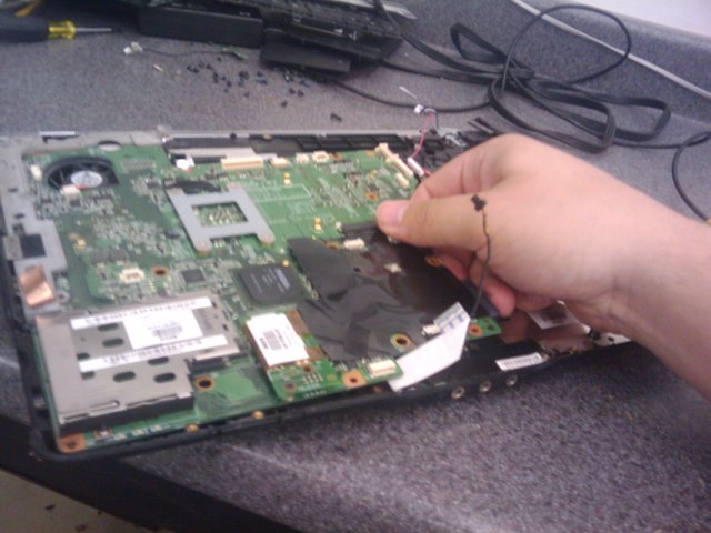
Step 26 : Do just like this. Take your time.

Step 27 : On this motherboard we have this IO guard. It will be loose, just take it off and set it aside.

Step 28 : The motherboard in all its glory. Now we are going to remove the heat sink/fan from the processor. This same heat sink/fan also cools the video chipset. The video chip and the processor sharing the same heat sink?

Step 29 : Open the Heat Sink
 |
Remove the screws in a diagonal pattern. Top left, bottom right, top right, bottom left. Then the screw on the side. |
Step 30 : Underneath the fan, you’ll see its connector. Remove this, and you can remove the whole thing.

Step 31 : Pulling the assembly off. On the right is your processor. On the left is the video chip. This is what we are going to reflow. Notice rubbery thing on top of the video chip. This is the thermal pad, and you don’t want to lose it. You will want to put it back when you are done, and it is very easy to mess up, so be careful when you remove it. Use your flathead.

Step 32 : Here it is without its thermal pad. This chip right here is what we are after, and what is responsible for the problems the computer is having. Now we are going to focus on isolating this chip with foil, so we can prevent the extreme heat from our heat gun from affecting the other components of the motherboard.

Step 33 : This is accomplished by using heavy duty aluminum foil. Here I’ve taken off a piece of foil big enough where I can fold it 3 times, I cut it off so it fits over the motherboard, then I apply it right over the top of the board, folding in the edges so it stays in place. Notice where the video chip Is, I’ve pressed down on it enough that you can actually see the chip.

Step 34 : Now, we take our razor, and we CAREFULLY cut around the video chip.

Step 35 : After cutting out the layers, I take a single layer of the foil I cut out and apply it to the chip itself. I then smooth it down very tightly, like how you see here. This will distribute the heat more evenly around the chip itself.
 |
| Now here’s a little trick I do to tell when I’ve reached the right temperature, this was told to me by a fellow laptop tech. You get your soldering iron and your solder, and then melt off a nice blob of it right on top of the chip itself. This acts as your temperature gauge. Whenever the solder starts melting, you know you are at the right temperature. |

Step 37 : This is how close you need to get once you start letting er rip at the highest setting. Remember, nice circular motions, gradual heat build up until you are at the maximum level. I take roughly about 60 seconds to get to the highest level, and at this point it takes about another 20 until I can see the solder melting. Once I start seeing the solder melt, I count to 5, then I set the gun to a lower setting for another 15 seconds, then I turn the gun off, set it aside, and then go do something for another 30 minutes. The internal solder has probably been melted down to this point, we want to give it plenty of time to cool and reset itself.

Step 38 : Now we can test it! Before we put the machine back together, it’s good to see if what we did actually worked. With this model we can do this fairly easily. Get your RAM, battery, heat sink/fan, sensor bar, and LCD. Attach the heat sink/fan first. Make sure you connect the cable that powers the fan. Then take a stick of ram, and put it into its slot. Then, hook the LCD to its connector, and the power button and ribbon cable from the sensor bar to their appropriate spots. Then carefully slide the battery to its connectors on the underside of the motherboard. Push the power button.

Step 39 : SUCCESS!!! When you see the splash screen you’re back in business.
From this point you put the computer back together, essentially following the steps I outlined above in reverse order. Remember to be careful, and don’t forget to put the cables back to where they were in the first place! It would suck to put the computer all the way back together and then realize that you forgot to connect the speakers! (Speaking from experience here)

Assemble with care and don't rush!!! :) Hope this HELPS!!!
Credits to :
Trick_M0nkey from http://hardforum.com/ for the full guide and picture!
Thanks for the effort to produce this detailed guide as it may come in handy considering how many PC/Laptops I'm asked to repair. The heat gun part could have many applications when placing a circuit board or component inside an oven is not an option.
ReplyDeleteA friend of mine asked me to repair his laptop because the screen would cut out sometimes when moved, and after disassembling and reassembling a number of times and testing all cables and connections I couldn't find the problem. I ended up just giving him an old PC of mine instead, though that laptop may have had a lose solder connection and I never thought to check or even consider a heat gun could work with foil to melt and reseat solder. I scavenged it for parts eventually so a bit late for the old thing now. ;)